Unit 5 - Electromagnetism
Magnetic Flux
$\Phi_B = \int \vec{B} \cdot d\vec{A} = BA \cos \theta
This equation is really similar to the equation for electric flux; just replace electric field $\vec{E}$ with magnetic field $\vec{B}$.
Gauss's Law for Magnetism
$\Phi_B = \int \vec{B} \cdot d\vec{A} = 0$
Every magnetic field line that enters must exit, so there cannot be a net flux.
Electromagnetic Induction
$|\epsilon|$ $=N$ $|\frac{d \Phi_B}{dt}|$ $= N$ $|\frac{d(BA\cos\theta)}{dt}|$
As shown above, a changing B-field, area of B-field, or angle can all affect the induced emf.
Direction of Induced EMF via Lenz's Law
- Determine if $\Phi_B$ is increasing or decreasing over time.
- Then, make $B_{induced}$ allow for no net B-field change.
- If $\Phi_B$ is increasing, then $B_{induced}$ will try to counteract this by going in the opposite direction of the given B-field.
- Likewise, if $\Phi_B$ is decreasing, then $B_{induced}$ will try to counteract this by going in the same direction of the given B-field.
- Thumb goes in the direction of $B_{induced}$, then fingers curl in the direction of induced current.
Motional EMF
$\epsilon = vBL$
When a loop is moving into a magnetic field, an EMF is induced from its movement through the field.
Induced Forces on Current-Carrying Loops
The torque of a loop as it spins around its center due to a magnetic field is equal to $\tau = NIAB \sin \theta$.
Inductors and Inductance
$\epsilon_L = -L \frac{dI}{dt}$
- Inductance is an opposition to a change in current in a conductor.
- This differs from a resistor, which opposes current in general, rather than a change in current.
- An inductor is a material with a known inductance.
Inductance of an Ideal Solenoid
$B_{solenoid} = \frac{\mu_0 N I}{\ell} \rightarrow L_{solenoid} = \frac{\mu_0 N^2 A}{\ell}$
This equation is not given, but is extremely useful!
Energy in an Inductor
$U_L = \frac{1}{2}LI^2$
LR Circuits
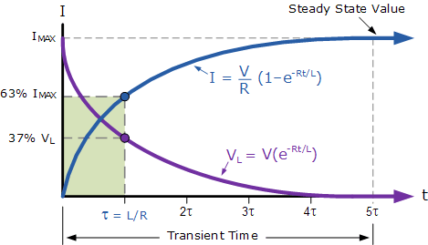
$I(t) = I_{max} \, (1 - e^{\frac{-Rt}{L}})$, $V(t) = V_{max} \, (e^{\frac{-Rt}{L}})$
- At $t = 0$, the inductor opposes the change in current, forcing the current to grow from zero to its final steady state.
- At $t = \infty$, the inductor acts as a wire and is essentially "invisible" to the rest of the circuit.
- In this type of circuit, the time constant $\tau = \frac{L}{R}$ is when the current is 63.2% of its final, steady-state current.
LC Circuits
$I_{max} = \frac{Q}{\sqrt{LC}}$
- In this circuit, the conductor discharges, and the magnitude of its electric field decreases. The inductor initially opposes the change in current before allowing it to flow within it, increasing the magnitude of its magnetic field.
- Then, the conductor begins to build up charge in the opposite direction in which it discharged due to the flow of current caused by the inductor.
- This continues forever, essentially in simple harmonic motion between the conductor and inductor.